Upgrading MapText Labeller
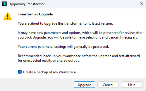
The MapTextLabeller instances in a workspace that were created in FME Form 2024 or older are not editable in FME Form 2025 and newer; however, these instances will still run during FME translations. To enable these instances to be editable in FME Form 2025 and newer, upgrade each instance by right-clicking on each MapTextLabeller and clicking on the Upgrade Transformer option in the pop-up menu. This will open the following dialog:
Clicking Upgrade will then open the following dialog showing the new version of the MapTextLabeller on the right:
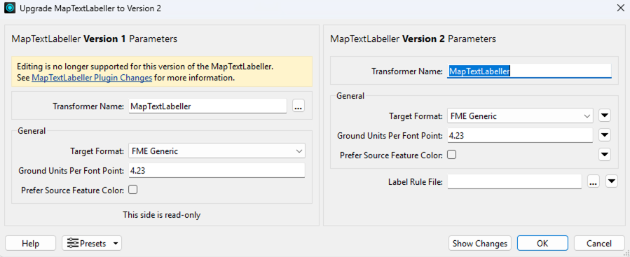
Clicking the Show Changes button will detail the changes between 2024 and 2025. Click Ok in order to upgrade the transformer.
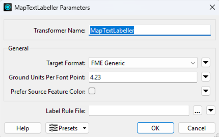
Once upgraded, open the MapTextLabeller’s properties to show the following:
The primary change to notice is that the Rule Configurations have been replaced with an external label rule file (.lrf). If a MapTextLabeller instance is run in FME 2024 or 2025, a default label rule file will be created that is named <workspace name>.lrf and stored in the same folder as the workspace. This file stores the set of inputs and the rule configurations that were previously stored in the workspace file. After the upgrade is performed, this default file can be selected for the Label Rule File property. After doing so, running the workspace translation will produce the same labeling results as before.
Note the following two limitations for this upgrade path:
When a translation is run with a MapTextLabeller version 1 instance, it can only write the layers to it for which there is data passed into the MapTextLabeller. For these layers, the Label Manager configuration that is stored in the workspace will be connected to these input layers. However, once you upgrade to version 2, the Label Manager configuration stored in the workspace is no longer available so additional layers that may be input into the MapTextLabeller at a later time because data becomes available for them will be added to the label rule file; however, these layers won’t be connected to any rules that existed earlier. Therefore, it’s best to run a translation initially with data present for all input layers so that the full label configuration that exists in the workspace is now available in the label rule file. However, if you do lose the association between an input layer and its rule, you can double-click in the User-Defined Layer Name column in the Label Rule File Editor and modify the name to be the name of the layer in the rules that existed earlier in the workspace.
In the unlikely scenario that two or more MapTextLabeller instances share the same rule layer names or placement rule names, only one of them will be emitted to the label rule file.
If a workspace contains multiple MapTextLabeller instances, then all inputs and rule configurations for all instances will be stored in the default label rule file. This default rule file can then be selected for each MapTextLabeller instance. Or you can make a copy of this rule file for each MapTextLabeller instance, update each copied rule file to contain only the layers for one MapTextLabeller instance and specify the updated rule file in the MapTextLabeller instance’s Label Rule File property in FME Form.
Setting up the MapText Labeller
Once an instance of a MapTextLabeller transformer is created, its input connections, labeling configuration, and output connections must be established.
Inputs
The set of features in each input (also called a feature layer or map layer) either serve as obstacles on the map to be avoided by placed labels and/or as sources of labels that can be defined.
The MapTextLabeller transformer creates an internal map view based on the features that are passed in via the transformer’s input connections. The transformer defines the map’s neatline (map boundary) by computing the minimum bounding rectangle around all of the features that are passed into it. For purposes of label placement, MapTextLabeller needs to know the line width of line features and area feature boundaries and the point symbols for point features. If this information is not explicitly attached to incoming features, then style defaults are used. To attach a feature style to all features in an input connection, use the MapText Styler transformer.
The MapTextLabeller automatically de-aggregates features and attempts to label the individual pieces. For more control over how labeling of aggregates is done, it is recommended that aggregates are split apart and possibly recombined in separate transformers prior to being fed into the MapTextLabeller. This additional processing can be performed using transformers such as the Deaggregator and AreaAmalgamator.
For FME 2025 and newer
Starting in FME 2025, there is only one input port on the MapTextLabeller named Input. All incoming connections are connected to this single port. Each incoming connection’s set of features fall into a FME layer identified either by the connection’s source reader name or source transformer name. The following example depicts this:
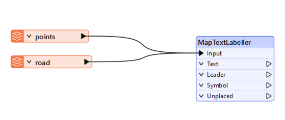
In this case, the map is composed of features in the points layer and the road layer.
For FME 2024
The following shows an example instance of a MapTextLabeller transformer with two input connections

In this case, the map is composed of features in the points layer and the road layer.
Labeling Configuration
Each input is viewed by the MapTextLabeller as a feature layer for which labeling configuration can be defined. The set of features layers compose the map.
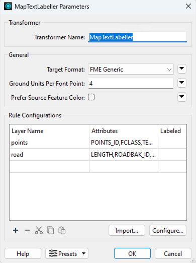
For FME 2025 and newer
The following dialog appears when the MapTextLabeller’s Properties button is clicked in FME Form:

To specify the labeling rules for labeling the map, select a label rule file. If no label rule file exists yet, the MapTextLabeller must be run first without a label rule file in order to generate a default one in which would be stored the set of FME input names (FME readers and/or transformers). The default label rule file is named <workspace name>.lrf and is stored in the same folder as the workspace file. During this initial run, the translation will abort with an error indicating that no label rule file has been specified.
If during a translation, it is detected that new FME inputs have been connected to a MapTextLabeller instance that are not present in the MapTextLabeller’s specified label rule file, then the label rule file will be updated with the new FME inputs, the user warned in the log file that an update has occurred, and the translation will proceed. The user can then open the updated label rule file in the Label Rule File Editor to configure the new FME inputs.
A label rule file is edited using the Label Rule File Editor. This external application is used to add label definitions to a new label rule file or update existing ones. To open the Label Rule File Editor, enter in the Windows search box “Label Rule File Editor” and click it when it appears. This will open the following dialog:
To create an empty rule file to specify for a MapTextLabeller instance, click on the menu File > New Empty Rule File, specify its name and where to create it. Then in FME Form, open the properties of a MapTextLabeller and specify for the Label Rule File property the newly created rule file. When a translation is run, this fie will be updated with new FME layers for which label definitions can then be configured in the Label Rule File editor.
To open an existing label rule file, click on the menu File > Open and select the label rule file to edit. An example of an opened label rule file is shown below:
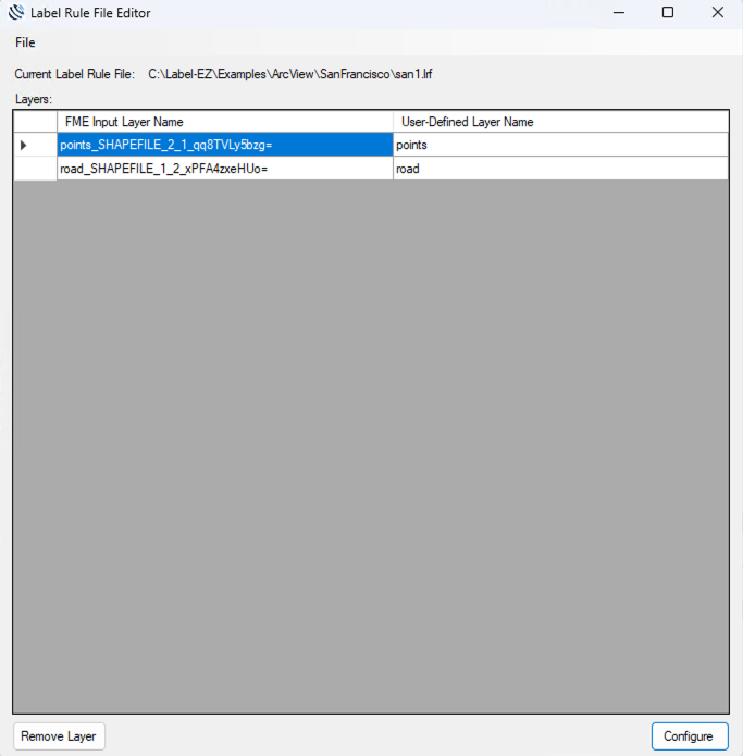
All FME inputs stored in the label rule file are presented in the Layers grid. Each layer has two names - a read-only FME Input layer name which identifies the source name of the FME input (incoming features from either FME readers or FME transformers) and a user-defined layer name. The additional random characters in each FME input layer name are added by FME in order to ensure that all FME inputs can be uniquely identified across a workspace. Each user-defined layer name is what appears in the Label Manager (described in the next section). Features from two or more FME input layer names can be combined into a single user-defined layer by assigning them all the same user-defined layer name. A layer’s user-defined name is edited by double-clicking on its cell in the grid, editing it, and then entering return.
To configure the layers for labeling, click the Configure button to open the Label Manager.
To remove a layer from the label rule file, select a row in the Layers grid and click the Remove Layer button.
To save a label rule file, open File > Save in the menu and either select an existing label rule file to overwrite or specify a new file to which to save the current label rules.
For FME 2024
The following dialog appears when the MapTextLabeller’s Properties button is clicked in FME Form.
Each input connection (feature layer) is shown in the Rule Configurations table. New layers can be added by either clicking the Import button and choosing a Reader or by connecting a Reader or the output of a transformer to the Connect Input port of the MapTextLabeller transformer. When the output of a transformer is connected to the Connect Port of the MapTextLabeller, a new map layer is created in the Rule Configurations with a default name. One can click on the default name and change it to a user-configured name. This will cause the line connecting the transformer output to the MapTextLabeller to be removed and show the map layer in red; however, at this point, the transformer’s output can be dragged again to the newly named map layer input port. One can also add a new layer using the + button found below the Rule Configurations table which will add a new row and enable the user to enter the map layer name and its set of attributes to include. This will create a new import port on the MapTextLabeller to which Readers or output of transformers can be connected. The - button found below the Rule Configurations enables a user to remove a map layer which will also remove it as an input port. A dot inside a row’s Labeled cell indicates whether a label definition has been configured for that row’s map layer.
To configure a label definition and a placement rule for each map layer that is to be labeled, click the Configure button to bring up the Label Manager.
For all FME versions 2024 and newer
Target Format
In order for the Labeller to accurately place the labels, it needs to know the actual physical height and length of each character in each label to properly fit the text on the map. Each display system implements its own algorithm for determining the physical height and width of each rendered character based on its user-specified font size. Because of this, it’s important to tell the Labeller the Target Format property whose renderer uses the display algorithm that matches the renderer of the application in which the placed labels will be viewed. For example, if the labels will be viewed in ArcGIS Pro, then choose ESRI ArcGIS for the Target Format.
There are special considerations to note for certain Target Format applications:
Bentley MicroStation Design - If colors are set within the MapText Labeller, the MicroStation writer will try to select the closest color from the seed file. To set colors properly, the desired font number from the seed file can be used for the Index Color parameter in the DGNStyler.
TrueType fonts should be specified in the seed file, since MapText Labeller only uses this type of font. The FME igds_font format attribute must be set to the font number from the seed file. The igds_font attribute can be set using an AttributeCreator, ValueMapper or another suitable transformer.
ESRI ArcGIS - Configured colors will not be properly assigned to shields and leaders (fme_color/fme_fill_color doesn't work). It is also not possible to write composite leaders to an ArcGIS Writer (a leader that is an aggregate of a polyline and filled polygon).
GeoMedia - Configured colors will not be properly assigned to shields and leaders (fme_color/fme_fill_color doesn't work). It is necessary to manually set the nominal scale and scaling to Paper in the GeoMedia workspace.
Ground Units Per Font Point
Labeller also needs to know the map scale at which to place the labels. This is defined by the Ground Units Per Font Point parameter. The following describes one way to compute this value:
Ground Units Per Font Point = scale / (72 *groundUnitsPerInch)
For example, if a map is to be labeled at a scale of 1:12000 and the units of the map are in meters, then since groundUnitsPerInch is 39.37meters/in and scale is 12000, then Ground Units Per Font Point would be 4.23.
Prefer Source Feature Color
The color of each output label is defined in its label style (more about this in a moment). However, if one wants to override this, and instead assign each placed label’s color based on its parent feature, if the parent feature possesses a color, then check the Prefer Source Feature Color checkbox.
The bulk of the labeling configuration occurs in the Label Manager. Let’s explore the Label Manager in the next section to learn how to configure each label definition and a placement rule for placing labels.